Inspire Creation | Smart Connection
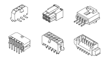
Surface-mount technology (SMT) connectors, like those from JST, provide significant advantages: they save valuable PCB space, streamline automated assembly, and deliver reliable connections in compact designs. These benefits make them ideal for applications ranging from wearables to industrial systems. Below, we’ll explore common JST SMT connector types and guide you through selecting the right one for your project.
Here’s a rundown of popular JST SMT connector types, organized by pitch size (smallest to largest), with essential specifications to aid your decision-making (orientation describes only SMT types):

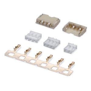
The JST SUR connector is a compact, 0.8 mm pitch wire-to-board insulation displacement connector (IDC), notable as the world’s first of its kind. It features a low-profile design and high contact reliability, requiring no crimping. Commonly used in high-density electronics, it excels in applications like laptops, smartphones, and wearable devices, where space is limited. Its heat-resistant housing supports reflow soldering, making it ideal for automated PCB assembly in consumer electronics and miniature digital products.

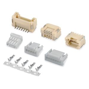
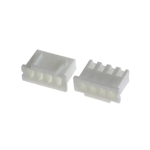
The JST SH connector, the world’s first 1.0 mm pitch crimp-style wire-to-board connector, boasts a compact, low-profile design. Its housing lance system ensures smooth contact insertion with smaller wires, while the high-pressure contact design delivers reliable, assured connections. Rated for 1.0 A and 50 V, this space-saving connector excels in high-density applications like wearables, laptops, drones, and medical devices, offering excellent performance and dependability in compact electronics.
The JST ACH connector is designed for DC power supply, offering a compact and low-profile build. Its 1.2mm pitch and small size (1.4mm height, 4.3mm width) make it suitable for space-limited applications. It features a locking mechanism for secure connections. This makes it ideal for LED lamps and small electronic devices needing reliable power in tight spaces.

The JST GH connector is a 1.25 mm pitch, wire-to-board connector designed for high-density applications. Featuring a secure locking mechanism and low insertion force, it ensures reliable, easy mating. Its compact, low-profile design suits small electronics. It’s widely used in devices like LCDs, PDPs, notebooks, and drones, where space-saving and dependable connections are critical.

The JST GHD connector is a compact, double-row wire-to-board solution designed for high-density PCB mounting. Its small size and reliable locking mechanism make it ideal for space-constrained electronics. Commonly used in flat-panel TVs, AV equipment, and other consumer devices, it ensures secure connections despite its miniature footprint. The GHD’s ease of use and durability cater to automated assembly processes, making it a top choice for manufacturers seeking efficiency and performance in tight layouts.

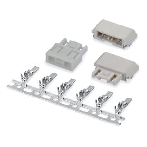
The JST ZH connector is a compact, low-profile component widely used in consumer electronics, industrial controls, medical equipment, and hobbyist projects. Its small size suits space-limited applications, while its reliable design and compatibility boost its versatility. From household appliances to industrial automation, it supports critical electrical connections in numerous electronic products.

The JST ZPD connector is a wire-to-board solution tailored for high-density PCB designs, featuring a dual-row structure and a secure lock mechanism. It offers low insertion force and a smooth mating experience, ensuring dependable connections. With excellent resistance to prying during insertion and extraction, plus a suction area for automated assembly, it’s ideal for applications like wearables, medical devices, and industrial equipment needing reliable, compact connectivity.
The JST ZE connector, a 1.5 mm pitch wire-to-board solution, excels in high-density PCB designs with its solid locking feature. It offers low insertion force and a tactile click for easy, reliable mating. The secure lock and large outer design ensure confidence in connection and release, while the housing prevents mismating. Exceptionally simple to assemble, it’s ideal for applications like consumer electronics, automotive systems, and industrial controls.

The JST PH connector is a low-profile, wire-to-board solution with a space-saving design, boasting a mounting height of 8 mm and a slim 4.5 mm width in its top-entry form. Its boxed-shaped shrouded header ensures high reliability, making it ideal for high-density PCBs in compact electronic equipment. Offering excellent functionality for PCB mounting, it’s widely used in applications like consumer electronics and small devices. SMT headers are available from 2 to 16 positions.

The JST PUD connector, a 2.0 mm pitch, dual-row wire-to-board solution, features a robust locking mechanism for reliable contact under vibration and stress. Its design ensures low insertion force and high precision alignment between housing and header, simplifying board mounting. With high-reliability contacts, easy operation, and optional boss headers for polarization, it’s ideal for automotive systems, industrial controls, and consumer electronics needing secure, efficient connections.

The JST XH connector is a highly reliable, versatile wire-to-board solution with a 2.5 mm pitch and a low-profile assembled height of 9.8 mm, perfect for space-sensitive designs. It features an original double-leaf contact design for secure connections, a box-shaped shrouded header, and an optional boss variant. Commonly used in home automation systems, LED lighting, and small appliances, it ensures dependable performance.

The JST VH connector is a small, field-proven solution for printed circuit boards, offering reliability and a large current carrying capacity. Its versatile design supports a wide range of signal, power supply, and output circuits, making it a trusted choice in consumer electronics. Common applications include power supplies in appliances, industrial equipment, and automotive systems, where its robust performance excels.
However, JST does not offer an SMT version of the VH series. In contrast, LDZY Electronics provides both straight and right-angle SMT versions, expanding options for surface-mount applications.
The JST LEB connector, tailored for LED lighting, boasts a low-profile height of 2.7 mm, optimizing space in compact designs. It supports horizontal PCB connections, incorporating a misalignment absorption mechanism (pitch direction only) to handle parallel setups and thermal expansion. High-pressure fork-type contacts ensure stable performance despite PCB movement, while a prevention feature stops incorrect insertion. Compatible with crimp-type sockets, it shares PCB layouts with plug and receptacle types. Common applications include LED lighting systems, automotive displays, and compact electronics requiring reliable, space-saving connections.
| Series Name | LDZY Alternative | Pin-to-Pin Pitch | Category | Pin rows | Circuit No. | Current (Amp) | Voltage (Volt) | Applicable Wire (AWG) | Shroud | Lock |
|---|---|---|---|---|---|---|---|---|---|---|
| SUR | A0800 | 0.8 mm (0.031 in) | wb | single | 2 to 22 | 0.5 | 30 | #32 | Yes | Yes |
| SH | A1001 | 1.0 mm (0.039 in) | ww | single | 2 to 20 | 1 | 50 | #32 to #28 | Yes | No |
| ACH | A1203 | 1.20 mm (0.047 in) | ww,wb | single | 1 to 5 | 2 | 50 | #32 to #28 | Yes | Yes |
| GH | A1257 | 1.25 mm (0.049 in) | wb | single | 2 to 15 | 1 | 50 | #30 to #26 | Yes | No |
| GHD | A1258 | 1.25 mm (0.049 in) | wb | dual | 10 to 40 | 1.25 | 50 | #32 to #26 | Yes | Yes |
| ZH | A1500 | 1.50 mm (0.059 in) | wb | single | 2 to 13 | 1 | 50 | #32 to #26 | Yes | No |
| ZPD | A1505 | 1.50 mm (0.059 in) | wb | dual | 10 to 40 | 2 | 100 | #28 to #24 | Yes | Yes |
| PH | A2001 | 2.0 mm (0.079 in) | wb | single | 2 to 16 | 2 | 100 | #32 to #24 | Yes | No |
| PHD | A2004 | 2.0 mm (0.079 in) | wb | dual | 8 to 34 | 3 | 250 | #28 to #22 | Yes | Yes |
| PA | A2007 | 2.0 mm (0.079 in) | wb | single | 2 to 16 | 3 | 250 | #28 to #22 | Yes | Yes |
| PUD | A2022 | 2.0 mm (0.079 in) | wb | dual | 8 to 40 | 3 | 250 | #28 to #22 | Yes | Yes |
| JWPF | C2013 | 2.0 mm (0.079 in) | ww,wb | single & dual | 2 to 8 | 3 | 100 | #26 to #22 | Yes | Yes |
| XH | A2501 | 2.50 mm (0.098 in) | wb | single | 2 to 20 | 3 | 250 | #30 to #22 | Yes | Yes |
| NH | A2501HA | 2.50 mm (0.098 in) | wb | single | 2 to 25 | 3 | 250 | #30 to #22 | No | Yes |
| EH | A2502 | 2.50 mm (0.098 in) | wb | single | 2 to 15 | 3 | 250 | #32 to #22 | Yes | Yes |
| XA | A2508 | 2.50 mm (0.098 in) | ww,wb | single | 2 to 38 | 3 | 250 | #28 to #20 | Yes | Yes |
| SM | C2505 | 2.50 mm (0.098 in) | ww | single | 2 to 39 | 3 | 250 | #28 to #22 | / | Yes |
| RCY | C2510 | 2.50 mm (0.098 in) | ww | single | 2 to 40 | 3 | 250 | #28 to #22 | / | Yes |
| VH | A3961 | 3.96 mm (0.156 in) | wb | single | 2 to 10 | 10 | 250 | #22 to #16 | Yes/No | Yes |
| LEB | B4000 | 4.0 mm (0.157 in) | wb,bb | single | 2 to 47 | 3 | 300 | #26 to #22 | Yes | Yes |
| NV | A5000 | 5.0 mm (0.197 in) | wb | single | 2 to 49 | 10 | 250 | #22 to #16 | No | Yes |
To select the best connector for your needs, follow these steps:
Pro Tips: Prioritize durability (e.g., LEB’s locking feature for vibration resistance), cost-effectiveness (XH is a budget-friendly option), and availability to keep your project on track.
JST SMT connectors span a wide range, from space-saving miniatures to high-power workhorses, each tailored to specific needs. By understanding the types and following a straightforward selection process, you can optimize your design. For personalized assistance, reach out to LDZY Electronics for help!
JST connectors, or Japan Solderless Terminals, are essential in electronics for their reliability and versatility. Whether you’re working on consumer electronics, automotive systems, or industrial equipment, there’s a JST connector designed for your needs. At LDZY Electronics, we supply high-quality alternatives to these popular connectors, ensuring you get the best fit for your project at competitive prices. In this post, we’ll explore the most common JST connector types, their specifications, applications, and how LDZY's alternatives can meet your requirements.
Below, we’ve listed the most popular JST connector types, ordered by pitch size from smallest to largest. For each, we’ve included LDZY’s alternative product, complete with a link to our product page for easy reference.
According to JST, it’s the world’s first 1.0mm pitch crimp style connector. It’s a single row wire to board connector system. 2-20pin. Compact and low profile design.
Part numbers:
| Description | Part Number | Note |
| Housing, with flange | SHR-02V-S-B (2pin) SHR-20V-S-B (20pin) | |
| Housing, without flange | SHR-02V-S SHR-15V-S (15pin) | |
| Terminal | SSH-003T-P0.2-H | 32~28 AWG |
| Header, top entry | BM02B-SRSS-TB (2pin) BM16B-SRSS-TB (16pin) | |
| Header, side entry | SM02B-SRSS-TB (2pin) SM20B-SRSS-TB (20pin) |
JST GH is a single row wire to board connector system. 2-15pin. Developed for to PDP, LCD or small electronics equipments.
Part numbers:
| Description | Part Number | Note |
| Housing | GHR-02V-S (2pin) GHR-15V-S (15pin) | |
| Terminal | SSHL-002T-P0.2 | 30~26 AWG |
| Header, top entry | BM02B-GHS-TBT (2pin) BM15B-GHS-TBT (15pin) | |
| Header, side entry | SM02B-GHS-TB (2pin) SM15B-GHS-TB (15pin) |
JST ZH is a single row wire to board connector system. 2-13 pin.
Part numbers:
| Description | Part Number | Note |
| Housing | ZHR-2 (2pin) ZHR-13 (13pin) | |
| Terminal | SZH-003T-P0.5 | 32~28 AWG |
| Terminal | SZH-002T-P0.5 | 28~26 AWG |
| Header, top entry, through-hole | B2B-ZR (2pin) B13B-ZR (13pin) | |
| Header, side entry, through-hole | S2B-ZR (2pin) S13B-ZR (13pin) | |
| Header, top entry, SMT | B2B-ZR-SM4-TF (2pin) B13B-ZR-SM4-TF (13pin) | |
| Header, side entry, SMT | S2B-ZR-SM4-TF (2pin) S13B-ZR-SM4A-TF (13pin) |
JST PH is a single row wire to board connector system. 2-16 pin.
Part numbers:
| Description | Part Number | Note |
| Housing | PHR-2 (2pin) PHR-16 (16pin) | |
| Terminal | SPH-002T-P0.5S | 30~24 AWG |
| Terminal | SPH-002T-P0.5L | 28~24 AWG |
| Terminal | SPH-004T-P0.5S | 32~28 AWG |
| Header, top entry, through hole | B2B-PH-K-S (2pin) B16B-PH-K-S (16ipn) | |
| Header, side entry, through hole | S2B-PH-K-S (2pin) S16B-PH-K-S (16pin) | |
| Header, top entry, SMT | B2B-PH-SM4-TB (2pin) B16B-PH-SM4-TB (16pin) | |
| Header, side entry, SMT | S2B-PH-SM4-TB (2pin) S15B-PH-SM4-TB (15pin) |
JST PA is a single row wire to board connector system. 2-16 pin.

Part numbers:
| Description | Part Number | Note |
| Housing | PAP-02V-S (2pin) PAP-16V-S (16pin) | |
| Terminal | SPHD-001T-P0.5 | 26~22 AWG |
| Terminal | SPHD-002T-P0.5 | 28~24 AWG |
| Header, top entry, through hole | B02B-PASK-1 (2pin) B16B-PASK-1 (16pin) | |
| Header, side entry, through hole | S02B-PASK-2 (2pin) S16B-PASK-2 (16pin) | |
| Header, top entry, SMT | BM02B-PASS (2pin) BM15B-PASS (15pin) | |
| Header, side entry, SMT | SM02B-PASS (2pin) SM15B-PASS (15pin) |
JST XH is a single row wire to board connector system. 1-20 pin.
Part numbers:
| Description | Part Number | Note |
| Housing | XHP-2 (2pin) XHP-20 (20pin) | |
| Terminal | SXH-001T-P0.6N | 26~22 AWG |
| Terminal | SXH-002T-P0.6 | 30~26 AWG |
| Terminal | SXH-001T-P0.6 | 28~22 AWG |
| Header, top entry, through hole | B3B-XH-A (3pin) B20B-XH-A (20pin) | |
| Header, side entry, through hole | S3B-XH-A (3pin) S16B-XH-A (16pin) | |
| Header, side entry, SMT | S3B-XH-SM4-TB (3pin) S6B-XH-SM4-TB (6pin) | 3, 4, 6 pin |
JST EH is a single row wire to wire connector system. 2-15 pin.

Part numbers:
| Description | Part Number | Note |
| Housing | EHR-2 (2pin) EHR-15 (15pin) | |
| Terminal | SEH-001T-P0.6 | 30~22 AWG |
| Terminal | SEH-003T-P0.6L | 32~28 AWG |
| Terminal | SEH-002T-P0.6L | 30~26 AWG |
| Terminal | SEH-001T-P0.6L | 26~22 AWG |
| Header, top entry, through hole | B2B-EH (2pin) B15B-EH (15pin) | |
| Header, side entry, through hole | S2B-EH (2pin) S15B-EH (15pin) |
JST SM is a single row wire to wire connector system. 2-18 pin.

Part numbers:
| Description | Part Number | Note |
| Housing, female | SMP-02V-BC (2pin) SMP-18V-BC (18pin) | black |
| Housing, female | SMP-02V-NC (2pin) SMP-18V-NC (18pin) | white |
| Housing, male | SMR-02V-B (2pin) SMR-18V-B (18pin) | black |
| Housing, male | SMR-02V-N (2pin) SMR-02V-N (18pin) | white |
| Terminal, female | SHF-001T-0.8BS | 28~22 AWG |
| Terminal, male | SYM-001T-P0.6 | 28~22 AWG |
JST RCY is a space-saving and low-profile 2.5 mm pitch wire-to-wire connector.

Part numbers:
| Description | Part Number | Note |
| Housing, female | SYR-02T | |
| Housing, male | SYP-02T-1 | |
| Terminal, female | SYM-001T-P0.6 | 28~22 AWG |
| Terminal, male | SYF-001’T-P0.6 | 28~22 AWG |
JST VH is a single row wire to wire connector system. 2-11 pin.
Part numbers:
| Description | Part Number | Note |
| Housing | VHR-2N (2pin) VHR-11N (11pin) | |
| Terminal | SVH-21T-P1.1 | 22~18 AWG |
| Terminal | SVH-41T-P1.1 | 20~16 AWG |
| Header, top entry, through hole | B2P-VH (2pin) B10P-VH (10pin) | |
| Header, side entry, through hole | B2PS-VH (2pin) B10PS-VH (10pin) |
Each of these connectors—and their LDZY alternatives—offers unique advantages depending on your project’s requirements. From ultra-compact designs to high-power applications, there’s a solution for every need.
Selecting the best connector involves balancing several factors. Here’s a quick guide to help you decide:
For custom projects, LDZY Electronics offers tailored solutions, including discrete-wire cable assemblies and custom flat ribbon cable assemblies, ensuring your connectors fit perfectly with your cables.
To ensure your connectors perform reliably over time, follow these tips:
These practices will help extend the life of your connectors and prevent common issues.
Comparison of JST SH, GH, ZH, PH, PA, XH, XA, SM, EH, and VH series connectors. You can get all alternatives from LDZY Electronics.
Note: wb = wire to board, ww = wire to wire
| attributes \ series | JST SH | JST GH | JST ZH | JST PH | JST PA | JST XH | JST XA | JST SM | JST EH | JST VH |
|---|---|---|---|---|---|---|---|---|---|---|
| LDZY series | A1001 | A1257 | A1500 | A2001 | A2007 | A2501 | A2508 | C2505 | A2502 | A3961 |
| pitch | 1.0mm | 1.25mm | 1.5mm | 2.0mm | 2.0mm | 2.5mm | 2.5mm | 2.5mm | 2.5mm | 3.96mm |
| circuit size | 2 - 20 | 2 - 15 | 2 - 13 | 2 - 16 | 2 - 16 | 1 - 20 | 2 - 15 | 2 - 18 | 2 - 15 | 2 - 11 |
| current rating | 1A | 1A | 1A | 2A | 3A | 3A | 3A | 3A | 3A | 10A |
| voltage rating | 50V | 50V | 50V | 100V | 250V | 250V | 250V | 250V | 250V | 250V |
| applicable wire (AWG) | 32 - 28 | 30 - 26 | 32 - 26 | 32 - 24 | 28 - 22 | 30 - 22 | 28 - 20 | 28 - 22 | 32 - 22 | 22 - 16 |
| configurations | wb | wb | wb | wb | wb | wb | wb, ww | ww | wb | wb |
| single row | YES | YES | YES | YES | YES | YES | YES | YES | YES | YES |
| dual row | NO | NO | NO | NO | NO | NO | NO | YES | NO | NO |
| locking feature | NO | YES | NO | YES | YES | YES | YES | YES | YES | YES |
| through hole type | NO | NO | YES | YES | YES | YES | YES | / | YES | YES |
| SMT type | YES | YES | YES | YES | YES | YES | YES | / | NO | NO |
JST connectors are a trusted choice for countless electronics projects, and LDZY Electronics supplies high-quality alternatives to meet your specific needs. Whether you’re working on a compact device or a high-power system, our range of connectors—from the tiny 1002 (SH alternative) to the robust 3961 (VH alternative)—has you covered.
Need a custom solution? Visit our contact page to discuss your project with our experts. We’ll help you find the perfect connector and cable assembly for your application.
With LDZY's alternatives, you get the reliability of JST connectors with the added benefits of competitive pricing and tailored support. Let’s bring your next project to life together!
Molex connectors are a cornerstone of the electronics industry, prized for their reliability and adaptability in applications ranging from consumer gadgets to industrial machinery. Whether you’re an engineer designing a new circuit or a procurement specialist sourcing components, accurately identifying Molex connectors is critical to ensuring your project’s success. With numerous series and variations available, the identification process can seem daunting—but it doesn’t have to be.
This guide provides a detailed roadmap to identifying Molex connectors. We’ll cover their key features, offer a step-by-step identification process, recommend essential tools and resources, and highlight common mistakes to avoid. By the end, you’ll have the knowledge and confidence to select the right Molex connector for your needs.
Molex connectors are electrical connectors designed to link wires or cables to devices or other cables. Renowned for their durability and versatility, they serve a wide array of industries. Molex offers an extensive lineup of connector series, each tailored to specific requirements. This diversity makes precise identification essential to match the connector to your project’s demands.
Common molex connector series:
| Series Name | LDZY Alternative | Pin-to-Pin Pitch | Category | Pin rows | Circuit No. | Current (Max) | Voltage (Max) | Applicable Wire (AWG) | Shroud | Lock |
|---|---|---|---|---|---|---|---|---|---|---|
| Pico-EZmate | A1201 | 1.20 mm (0.047 in) | wire to board | single | 2 to 6 | 3 A | 50 V | 30 to 28 | Yes | Yes |
| PicoBlade | A1250 | 1.25 mm (0.049 in) | wire to wire wire to board | single | 2 to 15 | 2.5 A | 125 V | 32 to 26 | Yes | No |
| Picoflex | D2558 | 1.27mm (0.05 in) | wire to board | dual | 4 to 26 | 1.2 A | 250 V | 28 to 26 | No | No |
| Pico-SPOX | A1501 | 1.50 mm (0.059 in) | wire to board | single | 2 to 15 | 2.5 A | 250 V | 30 to 24 | Yes | No |
| MicroBlade | A2002 | 2.0 mm (0.079 in) | wire to board | single | 2 to 15 | 2 A | 125 V | 30 to 24 | Yes | Yes |
| Sherlock | A2008 | 2.0 mm (0.079 in) | wire to board | single | 2 to 15 | 2 A | 125 V | 30 to 24 | Yes | Yes |
| Duraclik | A2018 | 2.0 mm (0.079 in) | wire to board | single | 2 to 15 | 3 A | 125 V | 30 to 22 | Yes | Yes |
| Mini-SPOX | A2506 | 2.0 mm (0.079 in) | wire to board | single | 2 to 15 | 4 A | 250 V | 28 to 22 | Yes | Yes |
| SL Modular | A2541 | 2.54 mm (0.100 in) | wire to wire wire to board | single | 2 to 41 | 3 A | 250 V | 36 to 22 | Yes | Yes |
| C-Grid III | A2541HA | 2.54 mm (0.100 in) | wire to board | dual | 2 to 42 | 3 A | 250 V | 28 to 22 | Yes | Yes |
| KK 254 | / | 2.50 mm (0.098 in) | wire to board | single | 2 to 43 | 4 A | 250 V | 30 to 24 | Yes/No | Yes |
| Micro-Fit | C3030 | 3.0 mm (0.118 in) | wire to wire wire to board | single & dual | 2 to 44 | 8.5 A | 600 V | 30 to 18 | Yes | Yes |
| Spox 396 | A3960 | 3.96 mm (0.156 in) | wire to board | single | 2 to 46 | 7 A | 250 V | 24 to 18 | Yes | Yes |
| Mini Fit | C4255 | 4.20 mm (0.165 in) | wire to wire wire to board | single & dual | 2 to 48 | 9 A | 600 V | 28 to 16 | Yes | Yes |
| Mega-Fit | C5704 | 5.7 mm (0.2244in) | wire to wire wire to board | single & dual | 2 to 12 | 30 A | 600 V | 16 to 12 | Yes | Yes |
Selecting the correct Molex connector isn’t just a technical detail—it’s a safeguard against potential problems. Misidentification can result in:
Proper identification ensures seamless integration, optimal performance, and enhanced safety, saving time and resources in the long run.
To identify a Molex connector, you need to recognize its defining characteristics. Here’s what to focus on:
Step 1: Determine the Type
Step 2: Measure the Pitch
Grab a digital caliper and measure the distance between the centers of two adjacent pins. Accuracy matters—2.5 mm and 2.54 mm may seem similar, but they point to different connectors. Record your measurement in millimeters.
Step 3: Count the Number of Positions
Simply count the pins or slots. A 2-position connector has two pins, a 5-position has five, and so on. This helps narrow your options.
Step 4: Look for Markings or Labels
Inspect the connector for molded or printed details—part numbers (like 43025, 43045), series names, or the Molex logo. These hints can quickly identify the series.
Step 5: Compare with Known Molex Series
Match your findings with common Molex series using available tables or images. Cross-check the type, pitch, and positions, and consider the connector’s typical application for confirmation.
Avoid pitfalls and boost accuracy with these practical tips:
Accurately identifying Molex connectors is a vital skill for any electronics project. By mastering their key features, following a structured identification process, and leveraging the right tools, you can ensure compatibility and sidestep costly errors.
Still need help or exploring options beyond Molex? Contact LDZY Electronics for expert guidance and cost-effective connector solutions.
In the world of electronic design, selecting the right connector type is crucial for the success of your project. Two of the most common options are Surface-Mount Technology (SMT) and Through-Hole Technology (THT) connectors. Each has its own strengths and is suited to different applications. This guide will help you understand the differences between SMT and THT connectors and how to choose the best one for your needs.

SMT connectors are mounted directly onto the surface of a printed circuit board (PCB). They are soldered to pads on the board’s surface, allowing for a compact and streamlined design.
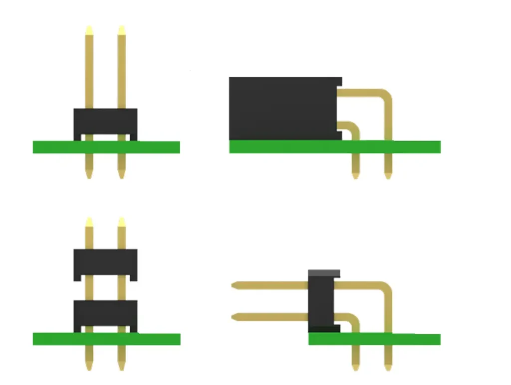
THT connectors are inserted through holes drilled into the PCB and soldered on the opposite side. They have leads that pass through the board, providing a strong mechanical bond.
Each connector type has its pros and cons:
When deciding between SMT and THT connectors, consider the following factors:
Choosing between SMT and THT connectors depends on your project’s specific requirements. If space savings and high-volume production are key, SMT may be the way to go. However, for applications demanding durability and easy maintenance, THT is often the better option.
Take the time to assess your project’s needs, considering factors like application type, production scale, and long-term reliability. If you’re unsure which connector type is right for you, contact us for expert advice or custom solutions tailored to your project.
When it comes to electronic connectors, every detail matters—especially the contact plating. At LDZY Electronics, we know that choosing the right plating can make or break your project’s performance. Contact plating ensures reliable electrical connections, prevents corrosion, and enhances durability. In this blog post, we’ll dive into three popular plating options—tin, gold, and selective gold—exploring their benefits, limitations, and ideal use cases. Whether you’re designing consumer electronics or high-stakes aerospace equipment, this guide will help you decide which plating is best for your needs. Let’s get started!
Tin plating is a go-to option for connector contacts, prized for its affordability and solid performance. The process involves electroplating a thin layer of tin over a nickel underlayer, which enhances durability and prevents oxidation. This coating prevents oxidation and maintains a stable electrical connection, making tin-plated connectors a staple in industries like automotive and consumer electronics.
Typical Thickness: 2.5 µm to 5 µm (100 µin to 200 µin).
Tin plating shines in budget-conscious projects where environmental conditions are controlled. If you’re looking for an economical yet dependable solution, tin might be the answer.
For applications where reliability is non-negotiable, gold plating stands out. This method deposits a thin layer of gold over a nickel underlayer, boosting durability while leveraging gold’s exceptional properties.. Gold’s exceptional properties make it a favorite in demanding industries like aerospace, medical devices, and high-end industrial equipment.
Typical Thickness: 0.38 µm to 0.76 µm (15 µin to 30 µin).
While gold plating is more expensive, its unmatched reliability justifies the investment in critical applications. At LDZY Electronics, we offer gold-plated connectors built to the highest standards, ensuring your project performs flawlessly.
Selective gold plating offers a smart compromise between cost and performance. Instead of covering the entire contact with gold, this method applies gold only to specific areas—like the mating surfaces—while using a cheaper material (often tin) elsewhere. It’s a tailored solution for clients who need gold’s benefits without breaking the bank.
Typical Thickness: 0.38 µm to 1.27 µm (15 µin to 50 µin) for gold areas; tin remains 2.5 µm to 5 µm.
Selective gold plating is popular in telecommunications, data centers, and other high-reliability fields where cost efficiency is a priority.
So, how do you pick the perfect plating for your connectors? It comes down to a few key factors:
At LDZY Electronics, we don’t believe in one-size-fits-all solutions. Our team works closely with you to assess these factors and recommend the best plating—whether it’s tin, gold, or a custom selective gold design.
Tin, gold, and selective gold plating each bring unique strengths to the table. Tin offers affordability and decent conductivity for everyday applications. Gold delivers top-tier reliability for mission-critical projects. Selective gold plating blends the two, providing cost-effective performance with strategic precision.
| Feature | Tin Plating | Gold Plating | Selective Gold Plating |
|---|---|---|---|
| Cost | Low | High | Moderate |
| Corrosion Resistance | Moderate (prone to oxidation) | Excellent (highly resistant) | Good (gold on key areas) |
| Conductivity | Good | Excellent | Good to Excellent (varies) |
| Wear Resistance | Low (softer, wears faster) | High (durable over cycles) | Moderate to High (gold areas) |
| Best For | Budget-friendly, mild conditions | Critical, harsh environments | Balanced cost and performance |
| Applications | Consumer electronics, automotive | Aerospace, medical, industrial | Telecom, data centers |
Not sure which option suits your project? LDZY Electronics is here to help. With years of expertise and a commitment to custom solutions, we’ll guide you to the perfect connector plating.
When it comes to electronic connectors, safety is a top priority. One critical aspect of ensuring that safety is the flammability rating of the materials used in their construction. For industries like automotive, aerospace, and consumer electronics, understanding the difference between UL94V-0 and UL94V-2 ratings can guide you in selecting the right connector for your project.
The UL94 standard, established by Underwriters Laboratories (UL), is a widely accepted test for evaluating the flammability of plastic materials used in electronic components, including connectors. These ratings ensure that materials meet safety standards, especially in environments where fire risks are a concern.
Two common ratings for connector materials are UL94V-0 and UL94V-2. Both indicate a level of flame resistance, but they differ in their performance under fire, testing requirements, and practical applications. Whether you’re an engineer, procurement specialist, or project manager, understanding these distinctions helps you make informed decisions about safety and compliance.
To understand what sets UL94V-0 and UL94V-2 apart, let’s look at how these ratings are tested and the criteria they must meet.
Before testing, materials undergo two conditioning processes to ensure consistent performance:
This dual approach ensures the material’s flammability is reliable under both normal and harsh conditions.
Both ratings use a vertical burn test:
The test measures:

Here’s how UL94V-0 and UL94V-2 differ:
Both conditioned sets must meet these standards for the material to earn its rating.
| Criteria | UL94V-0 | UL94V-2 |
|---|---|---|
| Self-Extinguishing Time | ≤ 10 seconds after each flame application | ≤ 30 seconds after each flame application |
| Flaming Drips | Not allowed to ignite cotton | Permitted, but cotton ignition ≤ 3 seconds |
| Total After-Flame Time (5 specimens, 10 applications) | ≤ 50 seconds | ≤ 250 seconds |
The flammability rating directly impacts the cost of connector materials, even when using the same base material like Nylon 66, a popular choice for connector housings.
The right rating depends on your project’s safety and performance needs:
The flammability rating influences more than just safety—it affects design and functionality:
Choosing between UL94V-0 and UL94V-2 involves weighing these factors against your project’s priorities.
The difference between UL94V-0 and UL94V-2 lies in their flame resistance, testing criteria, and practical applications. UL94V-0 offers top-tier safety with no flaming drips and faster self-extinguishing times, making it ideal for high-risk environments—at a higher cost. UL94V-2, while more affordable and allowing flaming drips, suits less demanding applications where cost efficiency is key.
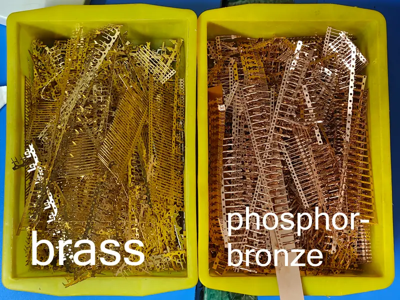
When selecting materials for electrical contacts in connectors, two copper-based alloys often stand out: Brass and Phosphor Bronze. These materials are widely used due to their unique properties, but choosing between them requires understanding their differences and how they align with your application’s needs. In this article, we’ll explore the properties, applications, and cost considerations of Brass and Phosphor Bronze contacts to help you make an informed decision.
Brass is an alloy primarily composed of around 65% copper and 35% zinc. The zinc content can vary, resulting in different types of Brass with tailored characteristics. Known for its versatility, good electrical conductivity, and affordability, Brass is a popular choice across various electrical and mechanical applications.
Phosphor Bronze, by contrast, is an alloy made of 90%+ copper, 2%–9% tin, and around 0.03% to 0.5% phosphorus. The inclusion of tin and phosphorus enhances its strength, durability, and resistance to wear and corrosion. This makes Phosphor Bronze a preferred material for applications where reliability and performance under stress are critical.
In the realm of electrical contacts, the choice between Brass and Phosphor Bronze significantly impacts the performance, longevity, and cost of connectors. Let’s dive into their key properties to better understand these differences.
Brass typically has a bright, golden-yellow hue due to its high zinc content, giving it a distinctive, shiny appearance. Phosphor Bronze, with its higher copper content and added tin, exhibits a duller, reddish-brown tone, often resembling aged copper, which can darken further over time depending on environmental exposure.

To evaluate Brass and Phosphor Bronze for electrical contacts, we’ll compare their electrical and mechanical properties.
Here is a comparison table:
| Property | Brass | Phosphor Bronze |
|---|---|---|
| Conductivity | Good (~28% IACS) | Slightly lower (~15–20% IACS) |
| Oxidation & Corrosion Resistance | Decent, tarnishes over time; plated (tin, gold, selective gold) for connectors | Superior, thanks to tin; plated (tin, gold, selective gold) for connectors |
| Strength & Durability | Moderate strength, suitable for low/medium stress | Higher tensile strength, excellent wear resistance |
| Flexibility & Fatigue Resistance | Less resilient under repeated stress | Excellent, withstands bending and stress without deforming |
| Temperature Tolerance | Performs well, but less stable in extremes | Better stability in extreme temperatures |
| Cost | Lower (65% copper, 35% zinc) | Higher (90%+ copper, 2%–9% tin, 0.03%–0.5% phosphorus) |
The choice between Brass and Phosphor Bronze contacts hinges on the specific demands of your application. Here’s how they’re typically used:
For example, a simple plug connector in a consumer device might use Brass, while a connector in an automotive system—exposed to vibration and temperature fluctuations—would benefit from Phosphor Bronze.
Cost is a key factor when choosing between Brass and Phosphor Bronze for electrical contacts.
The material used for electrical contacts plays a pivotal role in the performance and reliability of connectors.
Choosing the appropriate material isn’t just about meeting immediate needs—it’s about anticipating future challenges and ensuring product longevity.
In summary, Brass and Phosphor Bronze each bring distinct advantages to the table, suited to different applications:
When deciding between the two, consider your project’s specific needs:
By carefully evaluating these factors, you can select the material that best aligns with your project’s requirements and ensures optimal performance.
In the realm of electronic connectors, the selection of plastic materials for both housings and headers is pivotal for ensuring functionality, safety, and longevity. This post delves into the common materials used, their characteristics, and their suitability for specific applications, drawing from industry standards and manufacturer specifications.
Connector housings and headers serve distinct roles within electronic systems: housings provide mechanical support and electrical insulation for contact members, while headers, particularly those soldered onto printed circuit boards (PCBs), must endure high-temperature processes like reflow soldering. The choice of material impacts heat resistance, mechanical strength, electrical insulation, and cost, making it essential to align material properties with application requirements.
Connector housings, used in wire-to-wire and wire-to-board systems, typically are made in Nylon 66 (PA66) and PBT (Polybutylene Terephthalate).
Nylon 66 is a polyamide with high tensile strength, typically ranging from 80-100 MPa, and excellent heat resistance, with a heat deflection temperature (HDT) at 1.8 MPa of approximately 230-260°C for standard grades. Its melting point is around 260-270°C, making it suitable for high-temperature processes. It is flame-retardant, often rated UL 94V-0 or UL 94V-2, ensuring safety in electrical applications. However, it has moderate moisture absorption (1-3%), which can affect dimensional stability in humid environments. Its chemical resistance is good against hydrocarbons but fair against acids and bases.
PBT is a thermoplastic polyester with good mechanical strength, typically 50-70 MPa in tensile strength, and dimensional stability due to low moisture absorption (0.1-0.5%). Its standard HDT at 1.8 MPa is around 170-200°C, with a melting point of 220-230°C. Heat-stabilized grades can achieve HDT up to 220°C, making them viable for some connector applications. PBT offers excellent chemical resistance to acids, bases, and hydrocarbons, and flame-retardant grades are available with UL 94V-0 ratings.
| Property | Nylon 66 (PA66) | PBT |
|---|---|---|
| Heat Deflection Temperature (°C) | 230-260 | 170-200 (standard), up to 220°C (stabilized) |
| Tensile Strength (MPa) | 80-100 | 50-70 |
| Moisture Absorption (%) | 1-3 | 0.1-0.5 |
| Flame Retardancy | UL 94V-0/94V-2 | UL 94V-0 (with additives) |
| Chemical Resistance | Good (fair against acids/bases) | Excellent (acids, bases, hydrocarbons) |
| Cost | Higher | Lower |
Common materials for connector headers include PBT, PA66, PA6T, PA9T, and LCP. PBT and PA66 are typically used for through-hole type headers due to their temperature resistance, while PA6T, PA9T, and LCP are frequently employed for SMT headers, as they are well-suited for the reflow soldering process.
LCP offers exceptional heat resistance, with an HDT up to 300°C, low thermal expansion, and high dimensional stability. It excels in electrical properties, with tensile strength around 150-200 MPa, and has almost zero moisture absorption, ensuring excellent dimensional stability. It is flame-retardant, typically rated UL 94V-0, and offers excellent chemical resistance.
PA6T, a semi-aromatic polyamide, offers enhanced heat resistance with an HDT of 270-290°C, surpassing PA66. It has tensile strength similar to PA66, around 80-100 MPa, and lower moisture absorption (1-2%) compared to PA66. It is flame-retardant, often rated UL 94V-0 or UL 94V-2, and has good to excellent chemical resistance, better than PA66 due to its semi-aromatic structure.
PA9T, another high-performance polyamide, provides superior heat resistance (HDT up to 290°C), excellent toughness, and low moisture absorption (0.5-1%). Its tensile strength is higher than PA66, around 100-120 MPa, and it is flame-retardant, rated UL 94V-0 or UL 94V-2. It offers good to excellent chemical resistance, similar to PA6T, and is designed for extreme conditions.
Check above.
Check above.
| Material | HDT (°C) | Tensile Strength (MPa) | Moisture Absorption (%) | Flame Retardancy | Chemical Resistance | Cost |
|---|---|---|---|---|---|---|
| PA66 | 230-260 | 80-100 | 1-3 | UL 94V-0/94V-2 | Good | Medium |
| PBT | 220-240 | 50-70 | 0.1-0.5 | UL 94V-0 | Excellent | Low |
| LCP | up to 300 | 150-200 | almost 0 | UL 94V-0 | Excellent | Very High |
| PA6T | 270-290 | 80-100 | 1-2 | UL 94V-0/94V-2 | Good to Excellent | High |
| PA9T | up to 290 | 100-120 | 0.5-1 | UL 94V-0/94V-2 | Good to Excellent | High |
The choice of plastic materials for connector housings and headers significantly affects their performance and reliability. Nylon 66 (PA66) and PBT are commonly used for housings and through-hole type headers, providing a mix of strength and affordability. In contrast, LCP, PA6T, and PA9T are typically selected for SMT (surface-mount technology) headers, meeting the diverse demands of high-temperature and challenging environments. Understanding these material properties ensures connectors achieve the required standards for safety, durability, and functionality.