Inspire Creation | Smart Connection
In today’s fast-paced industries, reliability and durability are non-negotiable when it comes to cable solutions. Whether you’re in manufacturing, automotive, medical, or robotics, the cables you use can make or break your operations. This is where overmolded cable assemblies come in—a game-changer for businesses looking for robust, long-lasting cable solutions. But what exactly are overmolded cable assemblies, and why should you consider them for your next project? In this post, we’ll break down the basics to help you understand their value and applications.

At its core, an overmolded cable assembly is a cable system where a protective layer of plastic or rubber is molded directly over the cable and connector. This process creates a seamless, unified structure that enhances the cable’s strength and performance. The key components of an overmolded cable assembly include:
This integrated design not only protects the cable but also ensures it can withstand demanding conditions, making it ideal for a wide range of applications.
So, how are overmolded cable assemblies made? The process involves a technique called injection molding, where molten material is injected into a mold that contains the cable and connector. Here’s a simplified overview of the steps:
The result is a durable, one-piece cable assembly that’s built to last. At LDZY Electronics, we specialize in creating custom overmolded cable assemblies tailored to your exact needs—learn more on our overmolded cable assemblies page.
Why are overmolded cable assemblies so popular across industries? It’s all about their unique features and the benefits they deliver. Here are some of the standout advantages:
These features translate into real-world benefits, such as reduced downtime, lower maintenance costs, and enhanced safety for your operations.
Overmolded cable assemblies are used in a wide variety of industries, thanks to their versatility and reliability. Some of the most common applications include:
These examples highlight why businesses across sectors trust overmolded cable assemblies to keep their operations running smoothly.
If you’re still using traditional cable assemblies, you might be wondering: why make the switch? The answer lies in the superior performance and longevity of overmolded solutions. Unlike traditional cables, which often rely on separate strain reliefs or connectors that can wear out, overmolded cable assemblies offer a fully integrated design. This means fewer points of failure, better protection, and a longer lifespan.
At LDZY Electronics, we’ve seen firsthand how overmolded cable assemblies solve real-world challenges for our clients. Whether you need a cable that can withstand extreme weather, high flex cycles, or corrosive chemicals, our team has the expertise to deliver. Explore our capabilities on our overmolded cable assemblies page.
Overmolded cable assemblies are more than just cables—they’re engineered solutions designed to meet the toughest demands of modern industries. By combining durability, strain relief, and customization, they offer a reliable and cost-effective option for businesses looking to improve performance and reduce downtime.
Ready to see how overmolded cable assemblies can benefit your next project? At LDZY Electronics, we’re here to help you design and manufacture custom solutions that meet your exact specifications. Contact us today to discuss your needs and get started!
Welcome to our site, in this article, I am gonna show you how to crimp molex micro fit terminals.
Step by step.
You can see the title list of this article on the left of this page, feel free to jump to any titles that you are interested in.
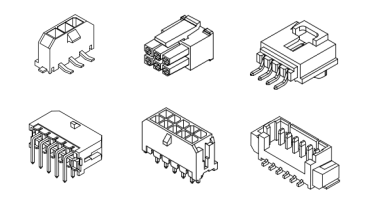
The Molex Micro-Fit is a 3.0mm pitch wire-to-wire and wire-to-board connection system. Both female and male terminals has two version in wire size accommodation. One type is for AWG24-AWG20 wires, and the other is for AWG30-AWG26 wires. In our tutorial, we will be using terminals for AWG24-AWG20.


If you have terminals in loose pieces, then you won’t be needing a terminal cutter. If you recevied terminals from a Chinese manufacturer, mostly like it’s in reel package.

Then a terminal cutter is needed to cut off terminals from the carrier strip. If you don’t have a cutter, use a scissors.

Just don’t use AWG24-AWG20 for a terminal which is applicable for AWG30-AWG26 wires, or use AWG30-AWG26 for a terminal which is applicable for AWG24-AWG20 wires. We will be using AWG20 wires (UL1007).

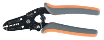
A wire stripper is a small, hand-held device used to strip the electrical insulation from electric wires. Feel free to use any stripper that does the work. We will be using IWISS FSA-0626B.
A crimping tool (also called crimper or crimping plier) is the tool used to deform the material and create the connection. Feel free to use any crimper that does the work. We will be using IWISS SN-2549.

After crimping completed, the crimped wires will go into the connector housing (with correct orientation). Let’s have dual row 8 pin male and female housings for instance.


Make sure you are following the following crimp criteria. It is important to ensure the quality of crimping.
Following are definitions of anatomy of a crimp termination from Molex. Acceptacne criteria are closely followed (in red color).

This material protrudes outside the insulation crimp after the terminal is separated from the carrier strip.
The cut-off tab length of molex micro fit terminal is 0.2-0.4mm.


The strip length is determined by measuring the exposed conductor strands after the insulation is removed. The strip length determines the conductor brush length when the insulation position is centered.
The wire strip length for molex micro fit terminal is 2.54-2.92mm. And avoid following symptoms.

It is formed on the edge of the conductor crimp acts as a funnel for the wire strands. This funnel reduces the possibility that a sharp edge on the conductor crimp will cut or nick the wire strands.
Bell mouth of molex micro-fit terminals is 0.2-0.4mm.

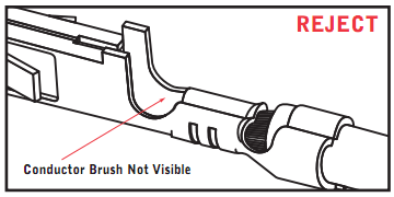
The conductor brush is made up of the wire strands that extend past the conductor crimp on the contact side of the terminal. This helps ensure that mechanical compression occurs over the full length of the conductor crimp.
There should be conductor brush, and it should not extend into the contact area.

This is the part of the terminal that provides wire support for insertion into the housing. It also allows the terminal to withstand shock and vibration. The terminal needs to hold the wire as firmly as possible without cutting through to the conductor strands. The acceptability of an insulation crimp is subjective and depends on the application. A bend test is recommended to determine whether the strain relief is acceptable for each particular application.
The terminal needs to hold the wire as firmly as possible without cutting through to the conductor strands.

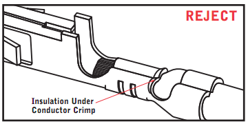
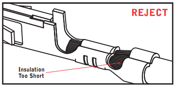
This is the location of the insulation in relation to the transition area between the conductor and insulation crimps. Equal amounts of the conductor strands and insulation needs to be visible in the transition area. The insulation position ensures that the insulation is crimped along the full length of the insulation crimp, and that no insulation is crimped under the conductor crimp.
Equal amounts of the conductor strands and insulation needs to be visible in the transition area.
Pull force testing is a quick, destructive way to evaluate the mechanical properties of a crimp termination.

Pull force testing results out of allowed range are good indicators of problems in the process. Cut or nicked strands in the stripping operation, lack of bell mouth or conductor brush, or incorrect crimp height or tooling will reduce pull force tests results. Wire properties and stranding, and terminal design (material thickness and serration design), also can increase or decrease the value of the results of a pull force levels.
Per UL486A, the crimped wires should pass the pull test at the following test value.
| Test Values For Pullout Test UL486A | |||
|---|---|---|---|
| Conductor Size | Pullout Force | ||
| AWG | mm2 | N | LBF |
| 30 | 0.05 | 6.7 | 1.5 |
| 28 | 0.08 | 8.9 | 2 |
| 26 | 0.13 | 13.4 | 3 |
| 24 | 0.20 | 22.3 | 5 |
| 22 | 0.324 | 35.6 | 8 |
| 20 | 0.519 | 57.9 | 13 |
| 18 | 0.823 | 89.0 | 20 |
| 16 | 1.31 | 133.5 | 30 |
| 14 | 2.08 | 222.6 | 50 |
| 12 | 3.31 | 311.5 | 70 |
| 10 | 5.261 | 356.0 | 80 |
| 9 | 8.367 | 400.5 | 90 |
Skip this step if you are using terminals in loose pieces. Keep cut-off tab length at 0.2-0.4mm.
The stripping tool we are using doesn’t have a wire stop. Thus we have to mark the strip point before stripping. The strip length is 2.54-2.92mm. So we mark at 2.73mm (average of 2.54 and 2.92) from the end.

Strip the marked wire, and use it as ruler to strip the rest wires. So you don’t have to mark every wire that needs to be stripped.
If the strands of wires scatter, use your fingers to twist them to centralize them for crimping process.

Check the stripped wires with your eyes under strip acceptance criteria.
Go to crimping acceptance criteria and inpect the crimped terminals with your eyes.
Apply an axial pullout force on the wire at a rate of 25±6mm (1±14inch) per minute.
When you are doing pull force testing, it is important that the jig or plier on the terminal side doesn’t grab the brush or conductor crmip area. And the jig or plier on the wire side doesn’t grap the insulation crimp area.

How to do pull force testing without professinal device or equipment?
You can use a plier to grab the terminal, and hang something that is 6KG (like a bucket with water ) on the wire. Then lift (when you feel the weight) the bucket from the ground by the plier at a very low speed. Once the bucket is off the ground, if it keeps for 10 more second, consider the test result is good.
It is not professional, but we can get a credible result from a credible mothed with limited resources.
The insertion orientation is that the lock of housing and seam of crimped terminals face the same direction. Both male and female apply.


That’s all about how to crmip moelx micro-fit terminals. What tips/points have I left out?
If you think the article is helpful, share it to help someone else like you.
Ribbon cable assemblies are used in a wide variety of industries and applications, from aerospace and defense to medical devices and consumer electronics. Designing a quality ribbon cable assembly that meets your specific requirements can be a complex proces. It involves several key steps to ensure that the assembly meets the required specifications and is optimized for the specific application.
In this post, we’ll outline six key steps to help you design a high-quality ribbon cable assembly that meets your needs and performs reliably in your application.
The first step in designing a ribbon cable assembly is to determine the requirements of the application, including the number of conductors, the pitch, the length of the cable, and any special features or requirements.
here are some specific steps to follow when determining the requirements for a ribbon cable assembly:
By taking these steps to define the requirements of the ribbon cable assembly, you can ensure that the assembly is optimized for the specific application and can meet the necessary electrical and mechanical performance requirements.
Once the requirements have been determined, the appropriate cable should be selected based on factors such as the number of conductors, the insulation material, and the AWG size. The cable should be selected based on its ability to meet the electrical and mechanical requirements of the application.
Following are common ribbon cable types. For detailed specifications, please check common ribbon cable specifications.

UL2651

UL 2651 rainbow

UL 2678

UL 2468

UL20080

glued wires
The connectors for the ribbon cable assembly should be selected based on the specific requirements of the application. The connectors should be compatible with the cable selected, and should be able to withstand the environmental conditions of the application.
Following are common IDC (insulation displacement connection) ribbon cable connectors. You can also use crimp style terminals & wire housings, like crimp style connectors of JST, molex, TE etc.


Strain relief is important to ensure that the ribbon cable assembly is protected from damage caused by pulling or bending. The strain relief method should be selected based on the specific requirements of the application and the type of connectors used.

Once the ribbon cable assembly has been designed, its electrical performance should be verified through testing to ensure that it meets the required specifications.
To verify the electrical performance of a ribbon cable assembly, several tests may be performed, including:
By performing these tests, you can verify the electrical performance of the ribbon cable assembly and ensure that it meets the required specifications for the specific application.
The mechanical performance of the ribbon cable assembly should also be verified through testing to ensure that it can withstand the environmental conditions of the application and is durable enough for its intended use.
When verifying the mechanical performance of a ribbon cable assembly, there are several factors that should be considered, including:
By testing the ribbon cable assembly for these mechanical factors, you can ensure that the assembly is robust and reliable enough to withstand the stresses of the application, and is optimized for long-term performance.
Whether you’re designing a custom cable assembly from scratch or working with a supplier to modify an existing design, these steps will help ensure that your ribbon cable assembly meets your requirements and performs as expected.
LDZY Electronics offers custom ribbon cable assemblies according customers’ specific requirements. Contact us today!