Inspire Creation | Smart Connection
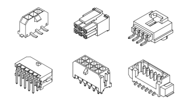
JST PH is a 2.0 mm pitch single-row wire-to-board connector system.
It is designed to meet the demand for high-density connection of internal wires to printed circuit boards. It is compact, highly reliable and low in cost.

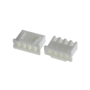
JST SH is a 1.0 mm pitch sing-row wire-to-board connector system. It is compact and low-profile.

LDZY electroincs has equivalents of both PH and SH series.
Both of them are crimp-style. Following is a comparison table of the two.
| attributes \ series | JST SH | JST PH |
|---|---|---|
| pitch | 1.0mm | 2.0mm |
| circuit size | 2 - 20 pin | 2 - 16 pin |
| current rating | 1A | 2A |
| voltage rating | 50V | 100V |
| applicable wire (AWG) | 32 - 28 | 32 - 24 |
| configurations | wire-to-board | wire-to-board |
| single row | YES | YES |
| dual row | NO | NO |
| locking feature | NO | YES |
| through hole type | NO | YES |
| SMT type | YES | YES |
JST PH and JST SH have differences in terms of pitch, circuit size, current rating, voltage rating, board connector types, and lock feature. Let’s check one by one.
Pitch size is a primary distinguishing factor between JST PH and JST SH connectors. JST PH connectors is 2.0mm (0.079 inches) pitch, while JST SH is 1.0mm (0.039 inches) pitch. This means that JST SH connectors have a higher pin density and are suitable for use in smaller form factor devices.
JST PH connectors are available in circuit sizes ranging from 2 to 16 contacts, whereas JST SH connectors can have anywhere from 2 to 15 contacts, and 20 contacts.
Current rating of JST PH connector is 2A per contact, and the voltage rating is 100V AC/DC. Making it suitable for use in applications with higher power requirements. Correspondingly, JST SH connector is 1A, and 50V AC/DC. Which is suitable for low-power applications.
JST PH connectors are available in both SMT and through-hole types, making them well-suited to a variety of applications. While JST SH connectors have only SMT type, which limits their use in through-hole PCB designs. However, JST SH connectors’ smaller pitch size makes them ideal for use in high-density PCB designs that require small and compact connectors.
JST PH connectors feature a friction lock mechanism, which helps to keep the connection between female and male secure and stable. This makes them ideal for applications where vibration or other external factors could potentially cause the connection to become loose.
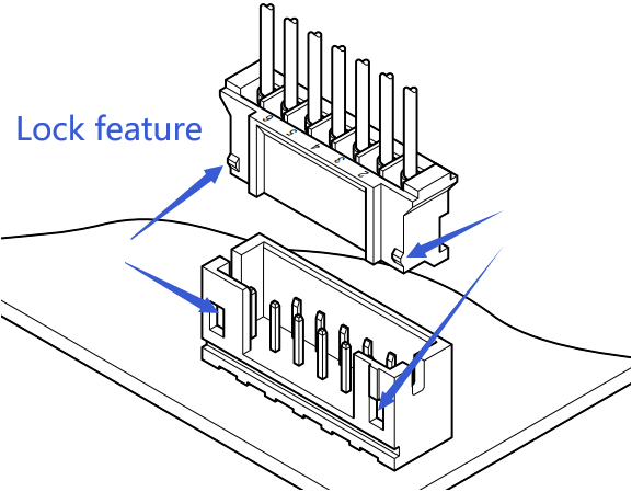
In contrast, JST SH connectors do not feature a lock mechanism, making them easier to connect and disconnect but also less secure than JST PH connectors. Therefore, designers need to carefully consider the specific requirements of their application when selecting a connector with or without a locking mechanism.
The PH series is frequently used in battery connections, such as for LiPoly batteries in RC models and 3D printers, due to its ability to handle moderate currents and its widespread availability.. The SH series, with its smaller size, is often found in high-density applications like small racing drones, WiFi equipment, and gaming consoles, where space and density are critical. This distinction highlights their complementary roles in electronics design.
JST XH connector is a single row 2.50mm pitch (pin spacing), crimp style wire to board connector system. Avaible circcuit size from 1 to 20. There are 4 types of header connectors (straight through-hole, right angle through hole, straight SMT, right angle SMT). Applicable wire size from AWG30 to AWG22. Current rating 3A, current voltage 250V.

The main difference between JST XH and JST PH connector is the pitch size and current rating. JST XH is 2.50 mm pitch, while JST PH is 2.0 mm pitch. The current rating of JST XH is 3A, while JST PH is 2A.
They are both single row wire to board connector system. With 4 types of PCB headers (straight through-hole, right angle through-hole, straight SMT, right angle SMT).
Following is the detailed comparison of the two.
| Attributes \ Series | JST XH | JST PH |
|---|---|---|
| LDZY series | A2501 | A2001 |
| pitch | 2.5mm | 2.0mm |
| circuit size | 1 - 20 | 2 - 16 |
| current rating | 3A | 2A |
| voltage rating | 250V | 100V |
| applicable wire (AWG) | 30 - 22 | 32 - 24 |
| configurations | wire to board | wire to board |
| single row | YES | YES |
| dual row | NO | NO |
| locking feature | YES | YES |
| through hole type | YES | YES |
| SMT type | YES | YES |
Many people ask “what is the difference between jst xh and xhp?”. But this is not a correct question.
JST XH is the family of the connetor series. While JST XHP is the plug housing (wire connector) of the it. JST XHP is a subset of JST XH.
Resources: JST XH Catalog (PDF)
Accordong to JST XH Catalog (PDF) , there is no JST XHR, but JST XHP. The “P” in “XHP” stands for “plug”. Means XHP is the plug housing of JST XH family. The “R” stands for “receptacle” (ex: JST SM catalog with both SMR and SMP), as you see on XH catalog, this is no XHR. It could be an old version name.
Following is the part number definition of XHP:

The JST PH and PHR connectors are often confused, but they’re essentially the same—PHR isn’t a distinct series.
“PH” is the official JST series name, a 2.0 mm pitch, wire-to-board, crimp-style connector, supporting AWG #30 to #24 wires and a 2 A current rating, ideal for compact applications like battery packs.
“PHR” is typically a shorthand or typo referring to the PH series’ receptacle housing (e.g., PHR-2, PHR-3), not a separate connector type.
So, there’s no real difference—PHR is just a part-specific reference within the PH family.
Just use a tooling (can be a ball-point pen) to press down the locking tang of the terminal. And then withdraw it by pull the crmiped wire out of the JST XHP housing.
Better not reuse the crmiped wire by only restoring the locking tang. Crimp a new terminal!

The JST PA and PH series—both with a 2.0mm pitch—are two popular choices. While they may seem similar at first glance, their differences can significantly impact your project. In this post, we’ll explore the features of JST PA and PH connectors and break down how to choose between them.

The JST PA series is built for durability and performance. With a 2.0mm pitch and a secure locking mechanism, it ensures a strong connection that won’t easily disconnect. Rated at 3A and 250V AC/DC, it’s well-suited for higher current needs. The PA is available in both through-hole and surface-mount (SMT) versions, offering flexibility in assembly.
Best for:
The JST PH series, also with a 2.0mm pitch, takes a simpler approach. It uses a friction lock for mating, making it easy to connect and disconnect. Rated at 2A and 100V AC/DC, it’s slightly less powerful than the PA but excels in compact designs. The PH is also available in both through-hole and surface-mount (SMT) versions.
Best for:
While both connectors excel in wire-to-board applications, their differences are key:
JST PA or PH—which is best for you? It’s all about your project’s needs. Choose the PA if you require durability, higher current capacity, and a secure lock. Opt for the PH if compactness and simplicity are more critical. With both offering through-hole and SMT options, you’ve got flexibility either way. Match their strengths to your design for the perfect fit.
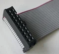
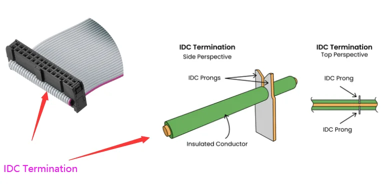
In the world of electronic connectors, efficiency and reliability are paramount. One solution that consistently delivers on both fronts is the use of IDC connectors in ribbon cable assemblies. These connectors are a go-to choice for engineers and designers looking to streamline their projects while ensuring secure, high-performance connections.

At LDZY Electronics, we specialize in crafting custom ribbon cable assemblies that meet the unique needs of our clients. In this post, we’ll explore what IDC connectors are, their key benefits, and the wide range of applications where they excel.
Insulation Displacement Connectors (IDC) are a type of connector that allows for quick and reliable connections without the need for stripping or soldering wires. Instead, IDC connectors use sharp contacts that pierce through the insulation of the ribbon cable, making direct contact with the conductors inside. This design is particularly effective for ribbon cables, which consist of multiple parallel wires arranged in a flat, flexible format.
Compared to other connector types, such as crimp or solder connectors, IDC connectors offer a faster and more efficient assembly process. They eliminate the need for individual wire preparation, making them ideal for high-volume production and applications where time and cost savings are critical.
The advantages of using IDC connectors in ribbon cable assemblies are numerous, making them a popular choice across various industries:
These benefits make IDC connectors a versatile and cost-effective solution for a wide range of projects.
IDC connectors are used in numerous industries due to their reliability and ease of use. Some of the most common applications include:
At LDZY Electronics, we offer custom ribbon cable assemblies tailored to the specific needs of these industries and more. Whether you need a standard solution or a fully customized design, our team can deliver.
When it comes to IDC connectors and ribbon cable assemblies, LDZY Electronics stands out for several reasons:
IDC connectors in ribbon cable assemblies offer a powerful combination of efficiency, reliability, and versatility. Whether you’re working in consumer electronics, automotive, telecommunications, or medical devices, these connectors provide a streamlined solution for your connectivity needs. At LDZY Electronics, we’re here to help you find the perfect custom solution for your project.
Ready to get started? Contact LDZY Electronics today for a quote or consultation, and let us bring your vision to life.
In this article, I am going to show you how to crimp a JST connector with a hand-crimping tool.
Step by step!
The are many types of JST connectors, we will be using JST XH for this tutorial. When you know how to crimp JST XH connector, you will get to know how to crimp other JST connectors.
Before you start to crimp, you should understand what a good crimp is.
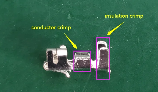
Then, get to know JST XH terminals.
The JST XH series offers three types of terminals, each designed for specific wire gauge ranging from AWG 30 to AWG 22.
Note that AWG (American Wire Gauge) defines a wire’s cross-sectional area, not its core diameter or insulation thickness. The AWG rating reflects the conductive core’s size—a bigger AWG number means a smaller wire, while a smaller AWG number indicates a larger wire. Insulation is a separate factor. Ensure your wire’s AWG and insulation align with the application’s requirements for optimal performance. Using a wire outside the recommended range can lead to poor connections or failures.
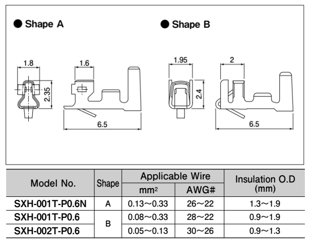
Following are crimp specifications.
SXH-001T-P0.6
| Strip Length (mm) | AWG | Insulation OD (mm) | Crimp Height (mm) | Tensile Spec (N) |
|---|---|---|---|---|
| 2.1~2.6 | 22 | 0.9~1.9 | 0.75±0.05 | 39.20 |
| 2.1~2.6 | 24 | 0.9~1.9 | 0.70±0.05 | 29.40 |
| 2.1~2.6 | 26 | 0.9~1.9 | 0.65±0.05 | 19.60 |
| 2.1~2.6 | 28 | 0.9~1.9 | 0.60~0.65 | 9.80 |
SXH-002T-P0.6
| Strip Length (mm) | AWG | Insulation OD (mm) | Crimp Height (mm) | Tensile Spec (N) |
|---|---|---|---|---|
| 2.1~2.6 | 26 | 0.9~1.3 | 0.62~0.67 | 19.60 |
| 2.1~2.6 | 28 | 0.9~1.3 | 0.60~0.65 | 9.80 |
| 2.1~2.6 | 30 | 0.9~1.3 | 0.57~0.62 | 7.80 |
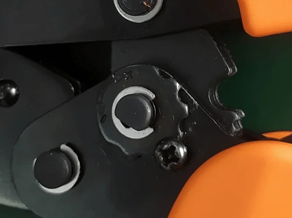
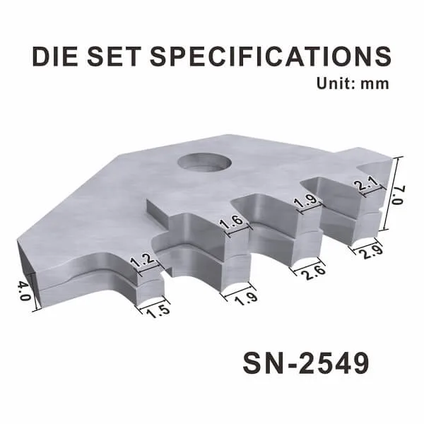
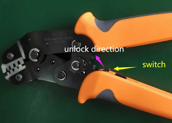
The crimping tool I will be using is IWISS SN-2549. It is for crimping AWG28-18 wires.
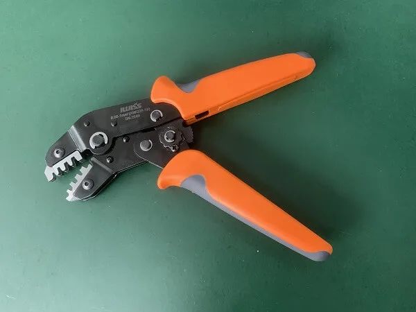
There is a gear to adjust the crimp height. You will have to remove the screw before adjusting it. Turn the gear clockwise (the “+” direction) to reduce the crimp height. And turn the gear anticlockwise (the “-” direction) to increase the crimp height. Install the screw back when you finish.
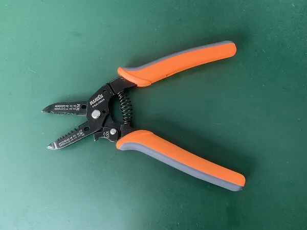
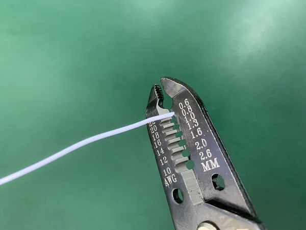
The wire stripper I will be using is IWISS FSA-0626. It is for stripping AWG22-AWG10 wires. But I found it OK to strip AWG24 wires.
The connector housings I will be using is JST XH equivalent connector. The terminals I will be using are JST SXH-001T-P0.6 equivalent. It is for AWG28-AWG22 wires. The wires I will be using are AWG24 UL1007.
As shown on the chart under different terminals in JST XH series, the strip length is 21.~2.6mm.
The strip length is important as we have to make sure:

Now let’s strip the wires.
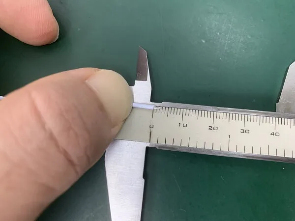
Measure the strip length after stripping.
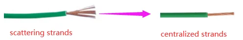
If the wire conductors scatter, center them with your fingers.
Narrow the gap between two tabs of insulation crimp till they are parallel (if you are using AWG22 wire, keep the gap a little wider).
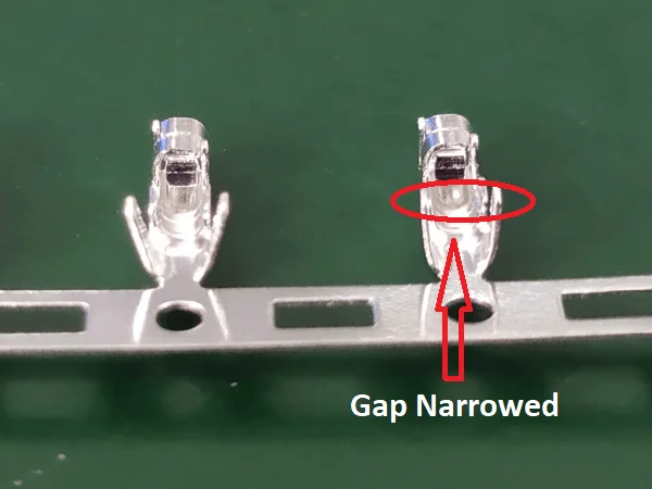
This is to prevent terminals from rotating during crimping.
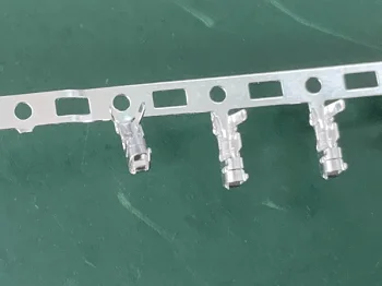
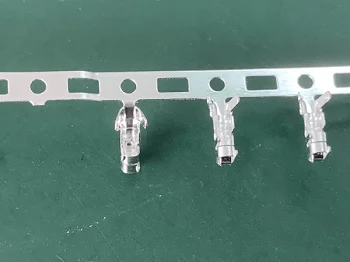
Remove terminals from the carrier strip by bending them up and down. It takes 3-5 bending to remove one terminal.
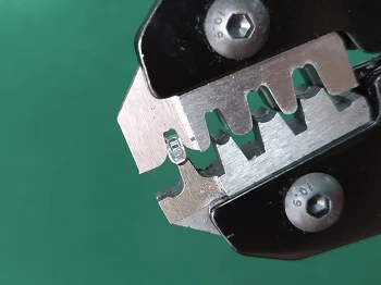
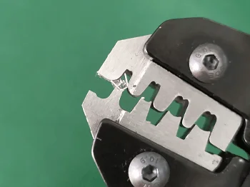
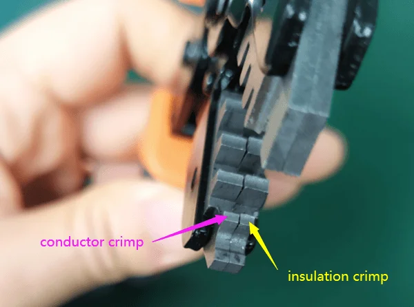
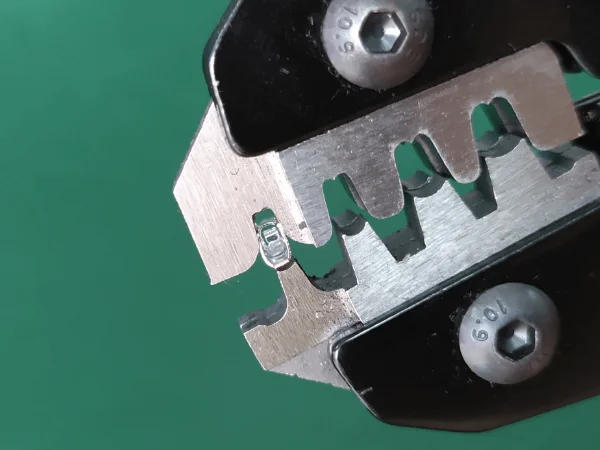
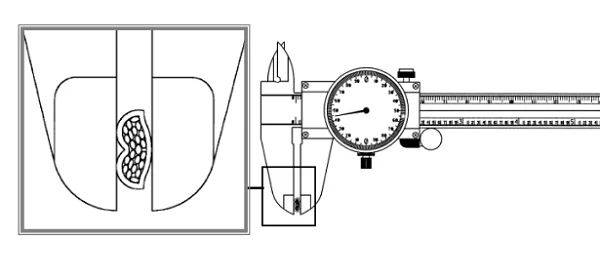
When crimping a JST XH terminal, the terminal should be crimped under the first jaw (4.0mm in thickness). The 1.5mm width part of the jaw is to crimp the wire insulation, and the 1.2mm width part is to crimp the wire conductor.
I am right-handed, so I will grip the crimper with my right hand, with the jaw pointing to my face. So I can see and adjust during crimping.
I will seize the mating side of the terminal between my thumb and index finger of my left hand.

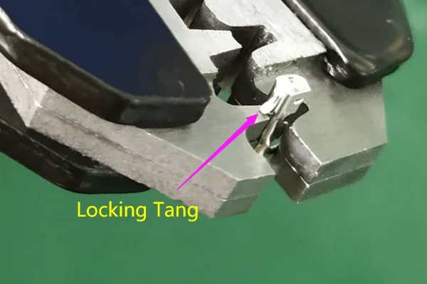
Put the terminal onto the anvil of the jaw, with the hook (locking tang) hooking the edge of the anvil (This is very important as if the hook goes into the crimping area, it will be crimped down. When you insert it into the connector housing, it will easily come out).
Now close the handles slowly, and stop before the tabs of the insulation crimp start to bend towards each other.
Now I can stop seizing the terminal, it will stay in the jaw. And use my left hand to insert a stripped wire into the terminal.
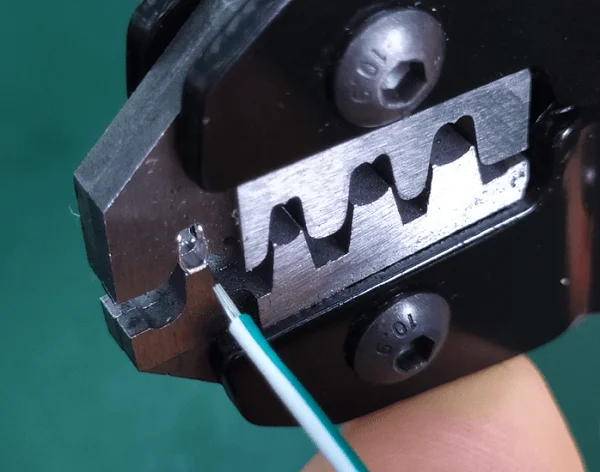
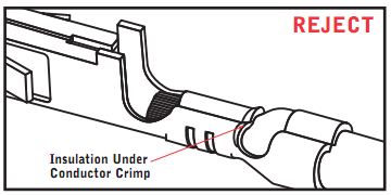
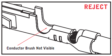
Control the insulation length in the terminal to make sure sufficient crimp on both insulation and conductor, and also insulation doesn’t go into the conductor crimp area. You might fail a few times before you manage to insert the proper insulation length.
Close the handles to finish the crimp. The handles will return to their original position itself.
Note: If there is something wrong and you would like to return the crimp handles, just use the switch between the handles.
Remove the terminal from the jaw.
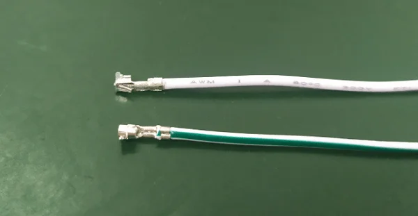
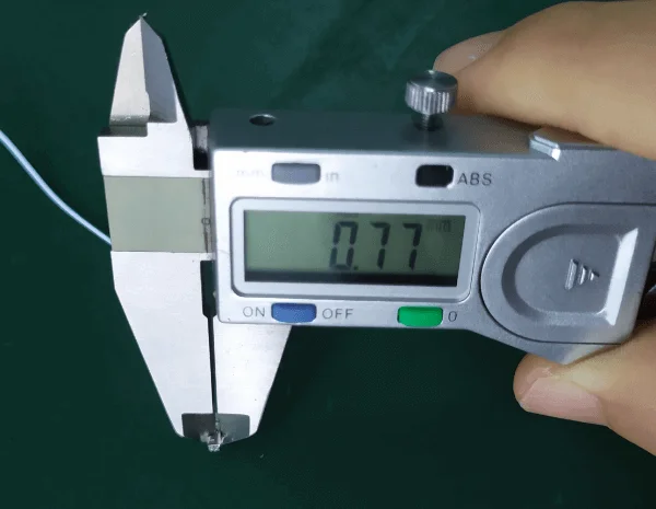
Measure the conductor crimp height with a caliper. The crimp height for AWG24 is 0.75±0.05mm.
When inserting the terminal, the locking tang of the terminal and the window of the connector housing should face the same direction.
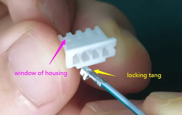
Insert the terminal, when you hear a click, it is done.

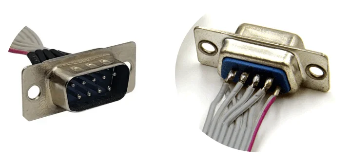
In the world of electronic connectors, choosing the right type for your application can make all the difference in performance, reliability, and cost-effectiveness. Among the many options available, D-Sub connectors paired with ribbon cables stand out for specific use cases. But when and why should you use them? In this post, we’ll explore the unique advantages of D-Sub connectors for ribbon cables, helping you make informed decisions for your projects.
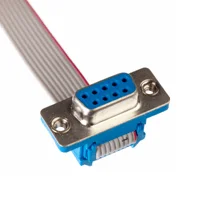
D-Sub connectors, named for their distinctive D-shaped metal shield, are a staple in the electronics industry. They come in various pin configurations, from 9 to 50 pins (standard), and are known for their robustness and versatility. These connectors are commonly used in applications ranging from computer peripherals to industrial machinery, where reliable signal transmission is crucial.

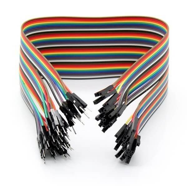
Ribbon cables, on the other hand, are flat, flexible cables with multiple conductors running parallel to each other. They are prized for their space-saving design and ability to keep wiring organized, making them ideal for internal connections in devices like computers, printers, and medical equipment.
So, when should you consider using D-Sub connectors with ribbon cables? This combination excels in scenarios requiring high-density connections, such as in data communication systems or legacy equipment where space is limited but multiple signals need to be transmitted simultaneously. Industries like industrial automation, telecommunications, and aerospace often rely on this setup for its proven reliability and ease of maintenance.
Compared to crimp style connectors, D-Sub connectors offer several distinct advantages. Their secure locking mechanism ensures a stable connection, reducing the risk of accidental disconnection. Additionally, their durability makes them suitable for harsh environments, and their ease of termination with ribbon cables simplifies assembly processes.
Why choose D-Sub connectors for ribbon cables? Beyond their physical attributes, these connectors are cost-effective and widely available, making them a practical choice for both small-scale and large-scale projects. They also comply with industry standards such as MIL-SPEC and IEC, ensuring compatibility and interchangeability across different systems.
However, selecting the right D-Sub connector involves considering several factors. Pin count, current rating, and shielding requirements must align with your application’s needs. Proper installation is key to preventing issues like signal interference, and regular maintenance can extend the lifespan of your connections. Space constraints can also be a challenge, but careful planning and the right connector choice can mitigate this.
At LDZY Electronics, we specialize in custom ribbon cable assemblies tailored to your specific requirements. Whether you need D-Sub connectors or alternative options like pin headers or female headers, our team can guide you through the selection process and provide solutions that meet your project’s unique demands. Explore our ribbon cable assembly page to learn more about our capabilities.
In conclusion, D-Sub connectors for ribbon cables are an excellent choice when you need reliable, high-density connections in space-constrained environments. By understanding their benefits and applications, you can make informed decisions that enhance your project’s performance and longevity. If you’re unsure whether D-Sub connectors are right for your needs, contact LDZY Electronics for a consultation or quote. Our experts are here to help you find the perfect solution.
Ribbon cables, also known as flat cables, are essential components in electronic assemblies, offering a compact and organized way to connect multiple signals between devices. However, the performance and reliability of a ribbon cable assembly heavily depend on how the cable is terminated. Termination refers to the method used to connect the cable’s conductors to a connector or another component. With options like IDC, crimping, and soldering, choosing the right method can be challenging. In this post, we’ll explore these three common ribbon cable termination techniques, their advantages, limitations, and applications, helping you make an informed decision for your project. At LDZY Electronics, we specialize in custom ribbon cable assemblies tailored to your needs.
Termination is the process of attaching a connector or other hardware to the end of a ribbon cable to enable electrical connectivity. A proper termination ensures a secure mechanical and electrical connection, preventing signal loss, interference, or failure in demanding applications. The choice of termination method depends on factors such as production volume, budget, environmental conditions, and the specific connectors used. Let’s dive into the three primary methods: IDC, crimping, and soldering.
Insulation Displacement Contact (IDC) is a widely used termination method for ribbon cables, particularly in mass production. In IDC, a connector with sharp metal blades pierces the cable’s insulation to make direct contact with the conductors inside, eliminating the need to strip the insulation manually.
This method is fast, efficient, and requires minimal labor, making it ideal for high-volume manufacturing. IDC offers several advantages, including cost-effectiveness, speed of assembly, and compatibility with standard ribbon cable connectors like D-sub or IDC-specific headers.
However, IDC has limitations—it is not suitable for high-vibration environments, as the connection may loosen over time, and it requires precise alignment with compatible connectors.
Common applications include consumer electronics, computer peripherals, and telecommunications equipment.
Crimping involves mechanically compressing a metal terminal or connector onto the ribbon cable’s conductors to create a secure electrical and mechanical connection. This method requires stripping the insulation from the cable and using specialized crimping tools to ensure a tight bond.
Crimping offers excellent durability, making it suitable for applications requiring robust connections, such as automotive or industrial equipment. Its versatility allows it to be used with a wide range of connectors, including custom pin headers and female headers.
However, crimping can be more labor-intensive than IDC and requires precise tools and skilled operators to avoid poor connections.
Common applications include automotive wiring harnesses, industrial control systems, and medical devices.
Soldering involves using a heated metal alloy (solder) to join the ribbon cable’s conductors to a connector or another component, creating a permanent electrical connection.
This method provides a robust and reliable connection, ideal for low-volume production or custom assemblies where durability is critical. Soldering is particularly useful when working with non-standard connectors or in applications requiring high electrical conductivity.
However, soldering has drawbacks—it is time-consuming, requires skilled labor, and poses a risk of thermal damage to the cable or nearby components if not done carefully. It is also less practical for mass production due to its labor-intensive nature.
Common applications include aerospace, military equipment, and prototype development.
To help you choose the right termination method, here’s a comparison of the three options based on key factors.
| Factor | IDC | Crimping | Soldering |
| Cost | Most cost-effective for high-volume production | Moderately cost-effective | Most expensive due to labor costs |
| Speed | Fastest | Moderately fast | Slowest |
| Durability | Less durable in high-vibration environments | High durability | High durability |
| Skill Level Required | Minimal | Moderate | High |
| Applications | Consumer electronics | Industrial uses | Custom or high-reliability applications |
At LDZY Electronics, we understand the nuances of ribbon cable terminations and can help you select the best method for your application. Whether you need IDC for rapid production, crimping for durability, or soldering for custom solutions, our team has the expertise to deliver high-quality, tailored ribbon cable assemblies.
Selecting the right ribbon cable termination method is crucial for ensuring the performance, reliability, and cost-effectiveness of your electronic assemblies. By understanding the strengths and limitations of IDC, crimping, and soldering, you can make an informed decision that aligns with your project’s requirements. If you need expert guidance or a custom solution, LDZY Electronics is here to help. Contact us today for a consultation or a quote.
Ribbon cables are a vital component in electronics, valued for their flat, flexible design that fits perfectly in tight spaces like computers, industrial machinery, and medical devices. At LDZY Electronics, we specialize in crafting custom ribbon cable assemblies, and a key part of our process is choosing the right materials for conductors and insulation. These choices affect everything from performance and durability to cost, so it’s crucial to get them right for your specific application. In this post, we’ll break down the common materials used in ribbon cables, the factors we consider when selecting them, and how we can help you find the best solution.
Ribbon cables have two main parts: conductors, which carry electrical signals, and insulation, which shields those conductors from environmental damage and prevents electrical interference. We carefully select materials for both to match the needs of your project—whether it’s high-speed data transfer, harsh conditions, or flexibility in confined spaces.
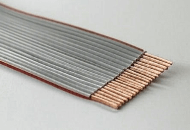
The conductor is the core of the cable, ensuring signals flow efficiently. Here are the materials we commonly use:
While rare, we can also use gold-plated conductors for ultra-specialized, high-reliability projects. For most cases, though, copper, tinned copper, or silver-plated copper meets the mark.
Insulation keeps conductors safe from moisture, chemicals, and wear while stopping electrical leaks. Here’s what we typically work with:
Each material has unique strengths, and we pick the one that fits your project’s demands.
We weigh several factors to ensure your ribbon cable performs at its best:
Balancing these elements lets us craft a cable that meets your technical and budget goals.
At LDZY Electronics, we know every project is different. Material selection is where we shine, tailoring each ribbon cable assembly to your exact needs—whether it’s flawless signal integrity, extreme temperature resistance, or cost efficiency. We offer a full range of options, from copper and PVC to silver-plated copper and Teflon, and our team collaborates with you to find the perfect mix of performance and value.
Picking the right conductor and insulation materials is critical to a ribbon cable’s success. Whether you need a budget-friendly option or a high-performance solution for tough conditions, we’ve got the expertise to make it happen. At LDZY Electronics, we’re ready to guide you through the process and deliver a custom assembly that fits your project perfectly. Reach out today for a consultation or quote—let’s build something great together.